Among the various techniques used in sheet metal bending, Z bending holds a special place for its versatility and functionality.
In this ultimate guide, we’ll take an in-depth look at sheet metal Z bending, covering its process, applications, tooling, design considerations, and tips for achieving the best results.
What is Sheet Metal Z Bending?
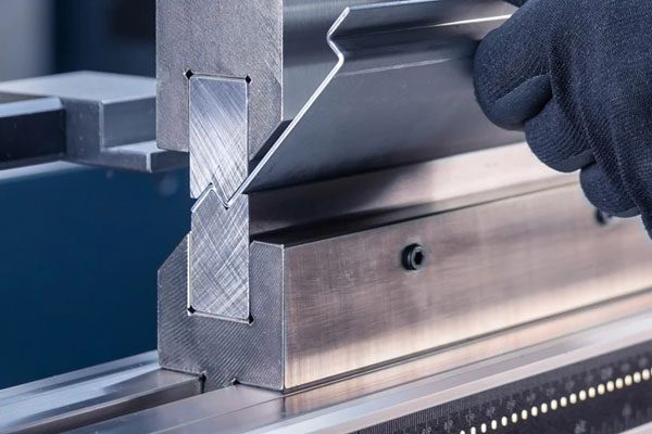
Z bending refers to a bending operation that forms the sheet metal into a “Z” shape profile. It involves two sequential bends in opposite directions, creating three parallel surfaces offset from each other.
Unlike simple V or U bends, a Z bend allows for creating stepped profiles. These are commonly used to make brackets, mounting components, stiffeners, and transition elements that fit into different planes without requiring welding or multiple parts.
How Does the Z Bending Process Work?
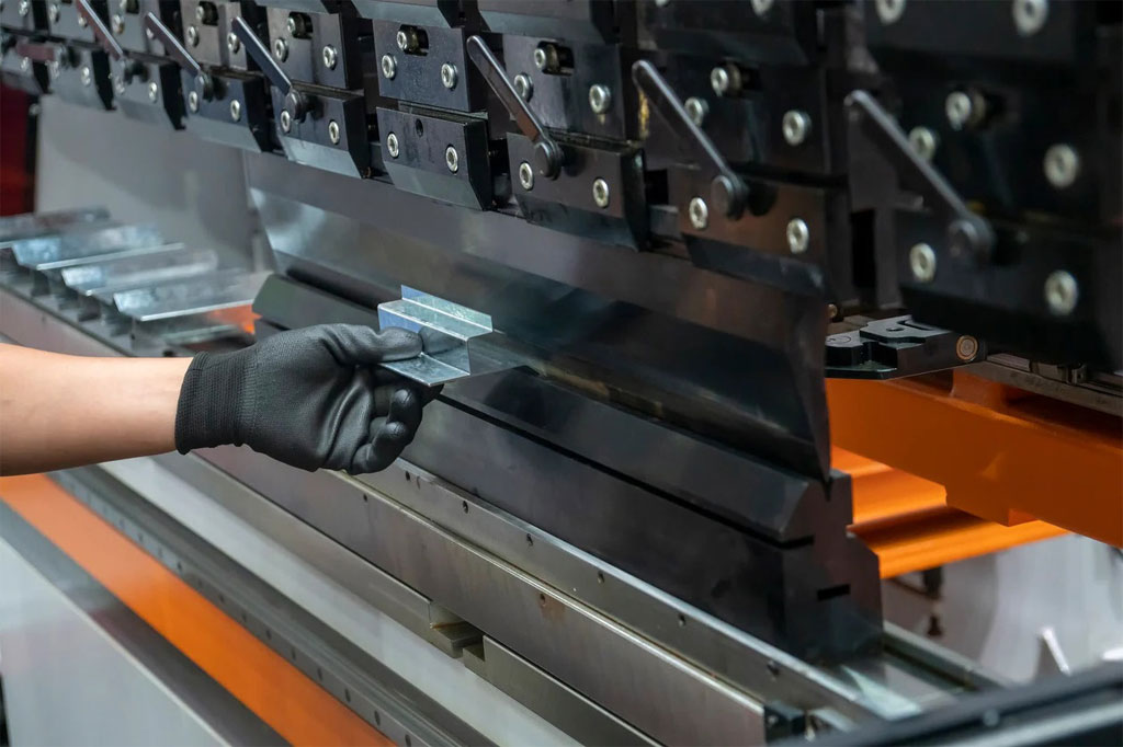
The Z bending process typically involves two main bending operations:
- First Bend: The sheet metal is bent at a specific angle (often 90 degrees) using a punch and die set.
- Second Bend: Reposition the workpiece and bend it in the opposite direction to form the Z shape.
In modern sheet metal shops, CNC press brakes are often used to automate and precisely control the bending sequence. Specialized Z-bending dies can even form both bends in a single stroke for thin sheet metal, although most standard operations involve two passes.
Common Bending Techniques Used for Z Bending
- Air Bending: The most flexible method, where the material does not fully contact the die. It allows variations in bend angles and material thickness.
- Bottom Bending (Coining): Offers high precision by forcing the material into the die shape.
- Offset Bending: Sometimes used synonymously with Z bending, it uses an offset die designed specifically to create a Z profile.
Typical Applications of Z Bending
Z bends are essential in many industries due to their ability to create functional offsets without assembly. Common applications include:
- Brackets and Mounting Hardware: Z bends provide surfaces for mounting parts at different heights.
- Enclosures and Panels: To create lips, flanges, or tabs for assembly without fasteners.
- Automotive Components: For structural supports, trims, and brackets.
- Electronics: Making casings, racks, and frames for electronic devices.
- Aerospace: Fabricating lightweight but strong structures that need dimensional transitions.
Tooling for Z Bending
Choosing the correct tooling is crucial for successful Z bends. Here’s what you typically need:
Press Brake
A press brake capable of multi-axis control offers the flexibility and precision required for complex Z bends.
Punches and Dies
- Standard Punch and Die: Suitable for simple two-stage Z bends.
- Offset Dies: Specially designed tools that form both bends in one hit for thin sheets.
- Custom Tooling: For intricate or high-volume production, custom punches and dies may be designed to optimize efficiency and minimize handling.
Material Considerations
Different materials behave differently during bending. Factors include:
- Thickness: Thicker materials may require wider dies and more force.
- Ductility: Materials like aluminum and mild steel are easier to Z bend than harder metals like stainless steel.
- Grain Direction: Always consider the material grain direction to prevent cracking during bending.
Design Considerations for Z Bending
Good part design is essential to avoid common pitfalls. When designing for Z bending, keep these principles in mind:
Bend Radius
- To avoid cracking, always maintain a minimum inside bend radius equal to the material thickness.
- Larger radii may be needed for brittle materials.
Bend Allowance and Bend Deduction
Bending changes the material’s effective dimensions. Calculating bend allowance and bend deduction accurately ensures your part’s final dimensions are correct.
Minimum Flange Length
Each bend requires a certain minimum flange length to accommodate the punch and die. A general rule:
- Minimum Flange Length = V-die opening × 0.5
Clearance
Allow enough clearance between adjacent bends to prevent tooling interference.
Tolerances
Real-world bending introduces small variations. Designing with reasonable tolerances (rather than ultra-tight ones) reduces production costs and rejects.
Tips for Successful Z Bending
Here are some professional tips to get the best results with Z bending:
- Prototype First: Always test your bend sequence on a prototype before full-scale production.
- Use CNC Programming: CNC-controlled press brakes improve repeatability and allow complex bend sequences without manual repositioning.
- Avoid Overbending: Bend angles often relax slightly after pressure is released (springback). Compensate with slight overbending based on the material type.
- Inspect Regularly: Use gauges or 3D scanners to inspect bend angles and offsets early during production.
- Collaborate with Fabricators: Engage your sheet metal supplier early during the design stage to optimize manufacturability.
Common Challenges in Z Bending (And How to Solve Them)
Even experienced fabricators sometimes encounter challenges. Here’s a quick troubleshooting guide:
| Problem | Cause | Solution |
|---|---|---|
| Material cracking | Too tight bend radius | Increase bend radius, use more ductile material |
| Inaccurate offsets | Wrong tooling or bend allowance calculation | Recheck die and punch selection, revise bend data |
| Wrinkling at bends | Overly thin sheet or sharp radii | Use stiffer material, adjust radii |
| Springback | Material elastic recovery | Apply overbending or bottom bending |
Conclusion
Mastering Z bending can significantly expand the possibilities in product design and manufacturing, offering efficient ways to create strong, lightweight, and functional parts.
By understanding the bending process, using the right tools, applying sound design principles, and following best practices, you can achieve precise, high-quality Z bends that meet demanding industrial standards.
Whether you’re a designer, engineer, or manufacturer, knowing how to leverage Z bending can give you a serious advantage in sheet metal fabrication.