A crucial factor in the design of CNC-machined components is torsional stiffness. It measures a part’s resistance to twisting when subjected to torque and is crucial in ensuring mechanical stability, accurate motion, and long-term reliability. In applications ranging from automotive drivetrains to aerospace components, insufficient torsional rigidity can lead to deformation, vibration, fatigue, and premature failure. This article explores the fundamental principles of torsional rigidity, methods for evaluating it, and design strategies to optimize CNC-machined parts.
Understanding Torsional Rigidity
Torsional rigidity, often represented as GJ/LGJ/LGJ/L, depends on the material’s shear modulus GGG, the polar moment of inertia JJJ, and the part’s length LLL. The torsional angle θ\thetaθ can be expressed as:
θ=TL/GJ
Where:
TTT = applied torque
LLL = length of the shaft/part
GGG = shear modulus of the material
JJJ = polar moment of inertia
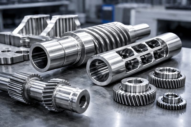
Higher torsional rigidity ensures that the component resists twisting under operational loads. This is particularly important for CNC-machined shafts, gears, spindles, and drive components, which must maintain precise motion and alignment.
Key Factors Influencing Torsional Rigidity:
- Material Properties: Steel, titanium alloys, aluminum, and composites each have different shear moduli.
- Cross-Section Geometry: Circular, square, rectangular, and hollow sections have different torsional characteristics.
- Length and Shape: Longer parts or components with variable cross-sections are more prone to torsional deflection.
- Machining Tolerances: CNC accuracy, surface finish, and residual stresses influence the final torsional behavior.
Choosing Materials with High Torsional Rigidity
The first stage in creating pieces that are resistant to torsion is selecting the appropriate material. Materials with a higher shear modulus, GGG, generally provide better torsional stiffness. Table 1 summarizes typical engineering materials used in CNC-machined parts and their shear moduli.
Shear Modulus of Common Engineering Materials
| Material | Shear Modulus GGG (GPa) | Typical Applications |
| Steel (AISI 1045) | 79 | Shafts, gears, spindles |
| Stainless Steel (304) | 77 | Food machinery, medical instruments |
| Aluminum 6061-T6 | 26 | Aerospace components, lightweight frames |
| Titanium Alloy (Ti-6Al-4V) | 44 | Aerospace, biomedical implants |
| Carbon Fiber Composite | 30–50 | High-performance shafts, drone frames |
Design Consideration: For weight-sensitive applications, titanium or aluminum alloys may be preferred, but additional geometric optimization is often required to maintain rigidity.
Geometric Design Methods
The geometry of CNC-machined parts plays a pivotal role in torsional rigidity. Engineers can use several approaches to optimize cross-sectional design.
Solid vs Hollow Shafts
Hollow shafts are commonly used in mechanical design due to their high torsion-to-weight ratio. For circular sections, the polar moment of inertia JJJ is:
Solid shaft: J= πd4/32
Hollow shaft: J= π(d04-di4)/32
Where d = diameter,d0 = outer diameter, di = inner diameter
Polar Moment of Inertia Comparison
| Shaft Type | Outer Diameter (mm) | Inner Diameter (mm) | Polar Moment of Inertia JJJ (mm4^44) |
| Solid | 50 | N/A | 3.07×10^6 |
| Hollow | 50 | 30 | 2.83×10^6 |
Observation: Hollow shafts reduce weight while maintaining nearly the same torsional rigidity, making them ideal for automotive and aerospace components.
Variable Cross-Sections
CNC machining allows complex shapes with variable cross-sections. By increasing the diameter in high-stress regions or adding flanges, designers can locally enhance torsional rigidity without excessive material use.
Ribs and Webs
For non-cylindrical components like brackets or plates, adding ribs and webs increases torsional stiffness. These features redistribute torsional stress and reduce angular deformation.
Design Tip: Ensure fillets at rib intersections to minimize stress concentrations.
Analytical and Computational Methods
Analytical Calculations
For simple geometries, torsional rigidity can be computed using classical formulas. Rectangular sections require the St. Venant approximation:
Θ =TL/kGbh3
Where bbb and hhh are the width and height, and kkk is a geometric factor (0.1406–0.208 for typical ratios).
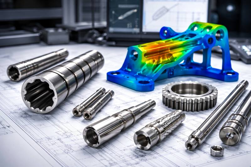
Finite Element Analysis (FEA)
For complex CNC parts, FEA is indispensable. Modern software like ANSYS, SolidWorks Simulation, and NX provides precise torsional stress distribution and deformation maps. FEA allows optimization of:
- Wall thicknesses
- Fillets and chamfers
- Complex rib structures
FEA vs Analytical Approach
| Method | Accuracy | Complexity | Suitable Use Cases |
| Analytical | Moderate | Low | Simple shafts and beams |
| FEA | High | High | Complex CNC-machined geometries |
Manufacturing Considerations in CNC Machining
Even with excellent design, machining parameters affect torsional rigidity. Key factors include:
- Residual Stresses: CNC operations like milling, turning, and drilling can induce residual stress. Stress-relieving treatments improve torsional performance.
- Surface Finish: Rough surfaces can initiate micro-cracks under torsional loads. Precision machining and polishing are essential.
- Tolerances: Tight geometric tolerances prevent eccentricity, which can reduce effective torsional rigidity.
Case Studies: CNC-Machined Components
Automotive Drive Shafts
Drive shafts transmit torque from the engine to the wheels. Torsional rigidity is provided while decreasing weight by using hollow steel shafts with appropriate wall thickness, which is essential for vehicle performance.
Aerospace Spindle Components
Spindles in aerospace actuators require precise torsional rigidity. Titanium alloys with ribbed geometries are CNC machined to resist high-torque loads without excessive weight.
Testing Methods for Torsional Rigidity
Direct Torque Testing
A torque wrench applies a known torque, and angular deflection is measured. This method is straightforward for quality control.
Dynamic Torsion Testing
Components are subjected to oscillatory torque to simulate real-world conditions. It reveals fatigue behavior and torsional resonance frequencies.
Common Torsion Testing Methods
| Method | Description | Typical Application |
| Static Torque Test | Apply torque and measure angular displacement | Shafts, couplings |
| Dynamic Torsion Test | Oscillatory torque to check resonance/fatigue | High-speed spindles, automotive drives |
| Digital Image Correlation | Uses cameras to measure twist and strain | Complex CNC-machined parts |
Design Guidelines to Maximize Torsional Rigidity
- Material Selection: Choose materials with a higher shear modulus for torque-critical parts.
- Optimized Geometry: Favor circular or tubular sections for shafts; use ribs for plates.
- Minimize Length: Shorter components have higher torsional rigidity.
- Avoid Sharp Corners: Fillets reduce stress concentrations and increase torsional lifespan.
- FEA Verification: Simulate real-world torque conditions before final machining.
Practical Considerations in CNC Machining
Complex geometries and exact tolerances are made possible by CNC machining, but designers must strike a balance between rigidity and:
- Weight constraints: Important for aerospace and automotive.
- Cost-effectiveness: Thicker walls increase rigidity but also material cost.
- Assembly compatibility: Torsional rigidity should integrate with bearings, couplings, and other components.
Torsional rigidity is a foundational parameter in CNC-machined components. By carefully considering material properties, geometry, and machining techniques, engineers can produce parts that resist twisting and maintain functional precision. Analytical formulas, FEA, and physical testing provide complementary methods for evaluating torsional performance. Torsionally rigid components that are properly engineered increase longevity, lessen vibrations, and enhance system performance.