
CNC machining surface finish affects part appearance, fit, sealing, wear resistance, corrosion resistance, and overall performance. Poor finish can cause assembly issues, friction, leakage, or early failure. This guide explains how surface finish is measured, what factors affect it, and how to choose the right finish without increasing unnecessary cost.
What Is CNC Machining Surface Finish?
CNC machining surface finish describes the texture, smoothness, and appearance of a machined surface. After milling, turning, drilling, grinding, or other machining processes, the tool leaves small marks on the material. These marks can be visible or microscopic, depending on the cutting method, tool condition, feed rate, spindle speed, and material type.
Surface finish is not only about appearance. It can influence:
- Friction between moving parts
- Sealing performance
- Bearing contact
- Fatigue strength
- Corrosion resistance
- Coating adhesion
- Cleaning performance
- Wear resistance
- Product appearance
- Assembly stability
For precision components, surface finish should be selected based on function, not only visual preference.
Why Surface Finish Matters for Precision Components
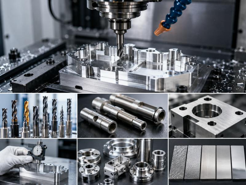
In precision machining, small surface differences can create big performance differences. Your component may need a smooth surface for sliding contact, a controlled roughness for coating adhesion, or a clean cosmetic finish for customer-facing equipment.
A shaft, for instance, could require a smoother surface to lessen wear and friction. A sealing face may need a controlled finish to prevent leakage. A mounting surface may need flatness and clean machining marks for stable assembly. A medical or food-grade part may need a smoother surface to support easier cleaning.
A correct surface finish helps you improve:
- Component life
- Mechanical performance
- Assembly accuracy
- Product reliability
- Visual quality
- Coating or plating results
- Customer acceptance
If you do not define surface finish clearly in your drawings, your supplier may use a standard machined finish, which may not match your application needs.
Common Surface Roughness Parameters
Surface finish is usually measured by roughness values. The most common parameter is Ra, which means average roughness. It calculates the average height difference between the surface’s tiny peaks and valleys.
Other parameters include Rz, Rq, and Rt, but Ra is the most widely used in general CNC machining communication.
| Parameter | Meaning | Common Use |
| Ra | Average surface roughness | Most common machining surface finish value |
| Rz | Average maximum height between peaks and valleys | Used when peak-to-valley control is important |
| Rq | Root mean square roughness | Used in more technical surface analysis |
| Rt | Total height of roughness profile | Used for stricter surface evaluation |
For most buyers, Ra is enough for standard CNC-machined parts. However, if your component has sealing, bearing, optical, or high-wear requirements, you may need more detailed surface specifications.
Typical CNC Machining Surface Finish Values
Different machining processes can achieve different surface finish levels. A rougher finish is easier and faster to produce, while a smoother finish usually requires slower feeds, sharper tools, finishing passes, grinding, polishing, or additional surface treatment.
| Surface Finish Level | Typical Ra Value | Common Application |
| Rough machined finish | Ra 6.3–12.5 μm | Non-critical surfaces, hidden areas, rough machining |
| Standard machined finish | Ra 3.2 μm | General CNC-machined parts |
| Fine-machined finish | Ra 1.6 μm | Precision components, better appearance, functional surfaces |
| Smooth finish | Ra 0.8 μm | Sliding surfaces, sealing areas, and high-quality visible parts |
| Very smooth finish | Ra 0.4 μm or better | High-precision sealing, bearing, polishing, and special applications |
For many CNC-machined components, Ra 3.2 μm is a common default finish. If you need better smoothness, you should mark it clearly on the drawing.
Factors That Affect CNC Machining Surface Finish
Many factors influence the final surface quality of your machined part. Understanding these factors can help you communicate better with your CNC machining supplier.
1. Cutting Tool Condition
Tool sharpness has a direct effect on surface finish. A sharp tool can cut cleanly, while a worn tool may create rough marks, burrs, vibration, or inconsistent surfaces.
Common tool-related issues include:
- Tool wear
- Chipped cutting edge
- Wrong tool coating
- Incorrect tool geometry
- Tool deflection
- Poor tool holding
For precision components, your supplier should control tool life and replace cutting tools before surface quality becomes unstable.
2. Feed Rate and Spindle Speed
Feed rate and spindle speed are key machining parameters. A higher feed rate can improve production efficiency, but it may also create more visible tool marks. A properly selected spindle speed can improve cutting stability and reduce roughness.
For better surface finish, CNC machinists often use:
- Lower feed rate
- Higher spindle speed
- Finishing pass
- Smaller depth of cut
- Proper coolant
- Stable toolpath strategy
However, better finish usually means longer machining time and higher cost.
3. Material Type
Different materials behave differently during machining. Aluminum is generally easier to machine and can achieve a clean finish. Stainless steel may work-harden and require careful cutting control. Plastics may melt, deform, or leave burrs if machining parameters are not correct.
Common material effects include:
- Aluminum: good machinability and bright finish
- Stainless steel: tougher to machine, may require slower cutting
- Brass: usually produces a smooth and clean finish
- Titanium: difficult machining, heat control is important
- Plastics: may need sharp tools and low heat
- Carbon steel: finish depends on hardness and cutting method
Your material choice should match both functional performance and achievable surface finish.
4. Machine Rigidity
A rigid CNC machine can reduce vibration and produce a more consistent surface. If the machine, fixture, tool holder, or workpiece is not stable, chatter marks may appear on the machined surface.
Chatter can cause:
- Wavy surface marks
- Poor dimensional accuracy
- Shorter tool life
- Noise during machining
- Poor repeatability
For high-precision components, stable fixturing and proper machining strategy are essential.
5. Coolant and Lubrication
Coolant helps reduce heat, flush chips away, and improve cutting conditions. Without proper coolant, chips may scratch the part surface or heat may damage the material.
Coolant can help improve:
- Tool life
- Surface smoothness
- Chip evacuation
- Dimensional stability
- Burr control
For some materials, dry machining or air blast may be preferred, but for many precision metal components, proper coolant use is important.
Surface Finish via CNC Milling
CNC milling removes material from a workpiece by rotating cutting blades. It is widely used for housings, brackets, plates, frames, molds, and complex precision components.
Milling surface finish is affected by:
- Tool diameter
- Tool path
- Step-over distance
- Feed rate
- Spindle speed
- Tool runout
- Cutting direction
- Number of finishing passes
For flat surfaces, face milling can produce a uniform pattern. For side walls and pockets, end milling marks may be visible. If you need a cosmetic surface, you should tell your supplier which surfaces are visible and what appearance is acceptable.
Common CNC milling finishes include:
- Standard machined marks
- Fine toolpath finish
- Circular face milling marks
- Brushed or bead-blasted finish after machining
- Polished surface for special parts
CNC Turning Surface Finish
CNC turning is commonly used for shafts, pins, bushings, sleeves, threaded parts, rings, and cylindrical components. The surface finish depends heavily on feed rate, tool nose radius, insert condition, and workpiece stability.
Turning can often produce a smooth and consistent surface on cylindrical parts. However, long or thin parts may vibrate during machining, causing chatter marks.
For a better turning surface finish, your supplier may use:
- Fine finishing inserts
- Correct tool nose radius
- Lower feed rate
- Tailstock or steady rest support
- Proper cutting speed
- Final finishing pass
If your part needs bearing contact, sealing contact, or sliding movement, you should clearly define the required Ra value on the drawing.
Surface Finish for Functional Areas
Not every surface on your part needs the same finish. To control cost, you should only require a smoother finish where it is necessary.
Critical functional surfaces may include:
- Bearing seats
- Shaft surfaces
- Seal grooves
- O-ring contact areas
- Sliding surfaces
- Mounting faces
- Connector surfaces
- Precision holes
- Thread start areas
- Optical or sensor contact surfaces
Non-critical hidden surfaces can usually use a standard machined finish. This helps reduce machining time and cost.
Surface Finish and Tolerance: What Is the Difference?
Surface finish and dimensional tolerance are different but related. Tolerance controls the allowed size variation of a part. The surface’s texture is controlled by surface finish.
A part can have a tight tolerance but a rough surface, or a smooth surface but loose tolerance. For precision components, you may need both.
For example:
- A shaft diameter may require ±0.01 mm tolerance.
- The same shaft surface may require Ra 0.8 μm.
- A sealing face may require flatness plus controlled roughness.
- A mounting surface may require both perpendicularity and fine finish.
When your part has a critical function, you should specify tolerance, flatness, surface finish, and inspection requirements together.
Secondary Processes for Better Surface Finish
Sometimes, CNC machining alone cannot achieve the required appearance or smoothness. In that case, secondary finishing processes may be used.
| Process | Purpose | Suitable Parts |
| Grinding | Achieve very smooth and accurate surfaces | Shafts, precision plates, bearing surfaces |
| Polishing | Improve smoothness and appearance | Medical, optical, decorative parts |
| Bead Blasting | Create a uniform matte texture | Aluminum housings, visible components |
| Brushing | Create directional surface lines | Panels, covers, decorative parts |
| Anodizing | Improve aluminum corrosion resistance and appearance | Aluminum precision components |
| Plating | Improve wear, corrosion, or conductivity | Steel, brass, copper, functional parts |
| Passivation | Improve stainless steel corrosion resistance | Medical, food, chemical components |
You should confirm whether the surface finish value applies before or after secondary treatment. For example, bead blasting changes surface texture, while anodizing can slightly affect dimensions and appearance.
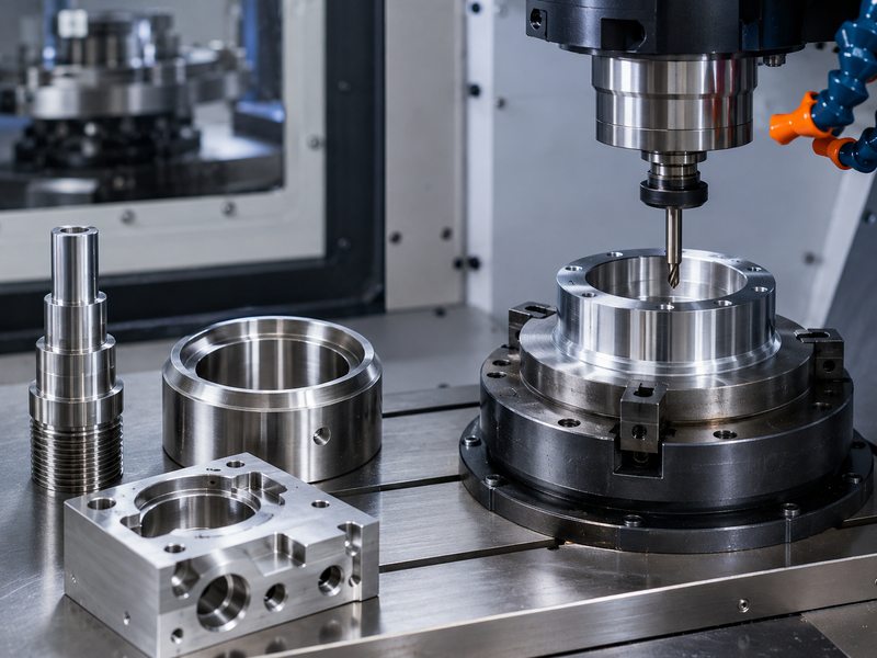
Surface Finish for Coating, Plating, and Anodizing
If your CNC-machined component needs anodizing, powder coating, painting, plating, or other surface treatment, the machined surface condition is very important.
A surface that is too rough may show visible defects after coating. In certain situations, an excessively smooth surface may decrease coating adhesion. Sharp edges, burrs, scratches, and machining marks may become more obvious after finishing.
Before surface treatment, your supplier should check:
- Burr removal
- Edge breaking
- Scratch control
- Surface cleaning
- Oil and chip removal
- Masking requirements
- Thread protection
- Dimensional allowance
For cosmetic aluminum parts, you may need bead blasting before anodizing to create a more uniform appearance.
How to Specify Surface Finish on Your Drawing
Clear drawing requirements help your CNC machining supplier understand exactly what you need. You should avoid vague terms such as “smooth finish” or “good surface” because different suppliers may understand them differently.
Better ways to specify surface finish include:
- Ra 3.2 μm unless otherwise noted
- Ra 1.6 μm on visible surfaces
- Ra 0.8 μm on the sealing surface
- No visible tool marks on the cosmetic face
- Bead blast + clear anodizing on exterior surfaces
- Remove burrs and break sharp edges
- Mask threaded holes before coating
You can also use surface finish symbols on your engineering drawing. For important parts, you should mark different finishes for different surfaces.
How to Balance Surface Finish and Cost
Better surface finish usually increases cost because it may require slower cutting, extra finishing passes, tool changes, inspection, polishing, grinding, or manual work.
To control cost, you should:
- Use standard finish on non-critical surfaces
- Apply fine finish only where function requires it
- Avoid unnecessary polishing
- Confirm cosmetic expectations early
- Allow visible tool marks on hidden surfaces
- Use bead blasting for a uniform appearance when suitable
- Discuss cost-saving alternatives with your supplier
A good supplier can help you find the right balance between performance, appearance, and budget.
Common Surface Finish Problems
Surface finish problems can come from machining parameters, material behavior, tool wear, fixturing issues, or post-processing mistakes.
Common problems include:
| Problem | Possible Cause | Solution |
| Chatter marks | Vibration, poor rigidity, long tool overhang | Improve fixturing, adjust speed/feed, reduce tool overhang |
| Burrs | Dull tool, wrong cutting parameters, soft material | Use sharp tools, deburr, and optimize toolpath |
| Scratches | Chip rubbing, poor handling, dirty surface | Improve chip removal, protect parts after machining |
| Uneven finish | Tool wear, inconsistent cutting, unstable setup | Control tool life and machining parameters |
| Visible tool marks | High feed rate, large step-over | Add a finishing pass or reduce feed |
| Poor coating appearance | Surface defects before coating | Improve cleaning, blasting, polishing, or pretreatment |
Finding the cause early can reduce scrap, rework, and delivery delays.
Inspection Methods for Surface Finish
For general components, visual inspection may be enough. For precision components, surface roughness should be measured with proper inspection tools.
Common inspection methods include:
- Visual inspection
- Touch comparison samples
- Surface roughness tester
- Profilometer
- Optical measurement
- Microscopic inspection
- Final inspection report
If surface finish is critical, you should request inspection records from your supplier.
Buyer Checklist for CNC Machining Surface Finish
Before you order CNC-machined precision components, you can use this checklist:
- Have you defined the required Ra value?
- Which surfaces are useful?
- Which surfaces are aesthetically pleasing?
- Do sealing or sliding areas need a smoother finish?
- Will the part be anodized, plated, painted, or polished?
- Are burrs and sharp edges controlled?
- Are threaded holes and masking areas marked?
- Is the finish requirement realistic for the material?
- Have you balanced finish quality and cost?
- Do you need inspection reports?
This checklist can help you avoid unclear requirements and improve supplier communication.
CNC machining surface finish affects appearance, friction, sealing, wear resistance, coating quality, corrosion protection, and assembly reliability. The best finish is not always the smoothest, but the one that matches your part’s function. By defining Ra value, critical surfaces, materials, and inspection needs clearly, you can improve part quality while controlling cost.