TIG welding, short for Tungsten Inert Gas welding, is a highly precise welding method favored for its ability to create strong, clean, and aesthetically pleasing welds. Commonly used in industries like aerospace, automotive, and food processing, TIG welding offers unmatched control over heat and filler material, making it ideal for thin metals, exotic alloys, and critical joints.
In this article, we provide a step-by-step overview of the TIG welding process, helping you understand the technical flow and critical considerations involved.
Step 1: Understanding the TIG Welding Principle
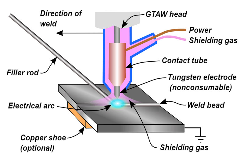
TIG welding uses a non-consumable tungsten electrode to generate an electric arc between the electrode and the workpiece. An inert shielding gas—usually pure argon—protects the weld zone from atmospheric contamination. The welder may or may not add filler metal manually depending on the joint type and thickness.
Key Components:
- Power Source: Usually DC or AC depending on the material.
- Tungsten Electrode: Non-consumable; maintains arc.
- Filler Rod (optional): Manually fed into the weld pool.
- Shielding Gas: Argon or argon/helium mixtures.
- Torch: Directs arc and shielding gas.
Step 2: Preparing the Materials
Proper surface preparation is critical in TIG welding.
Preparation Steps:
- Clean the Base Metal: Use a wire brush, acetone, or alcohol to remove contaminants.
- Deburr Edges: Ensure smooth joint edges to avoid arc instability.
- Select Joint Type: Choose between butt, lap, corner, or T-joints depending on the part geometry.
- Fit-up: Use clamps or tack welds to hold pieces in place, ensuring proper alignment and gap.
Step 3: Setting Up the TIG Welder
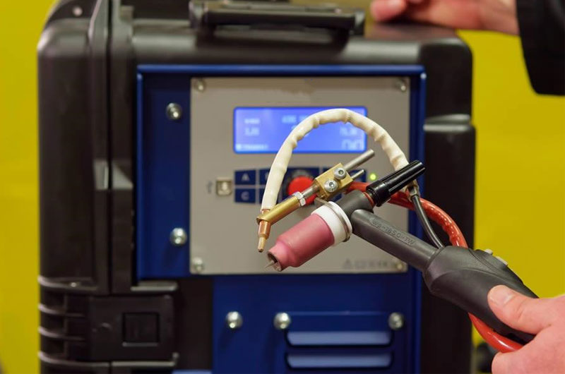
A correct setup ensures stable arc characteristics and consistent weld quality.
Adjust the Following Settings:
- Polarity:
- DCEN (Direct Current Electrode Negative) for steels, stainless steels, copper.
- AC (Alternating Current) for aluminum and magnesium.
- Amperage: Adjust based on material thickness (e.g., ~1 amp per 0.001″ of material thickness is a starting point).
- Gas Flow Rate: Typically 15–20 CFH (cubic feet per hour).
- Post-flow Time: 5–15 seconds to protect the tungsten and weld pool after arc termination.
Step 4: Electrode and Filler Selection
The choice of electrode and filler metal greatly influences weld quality and mechanical properties.
Tungsten Electrodes:
- 2% Thoriated (Red): Excellent arc starting, used for steel.
- 2% Lanthanated (Blue): Versatile; suitable for both AC and DC.
- Pure Tungsten (Green): Ideal for aluminum with AC.
Filler Rods:
- Match the base metal (e.g., ER70S-6 for carbon steel, ER308L for stainless steel, ER4043 or ER5356 for aluminum).
- Diameter usually ranges from 1/16″ to 3/32″.
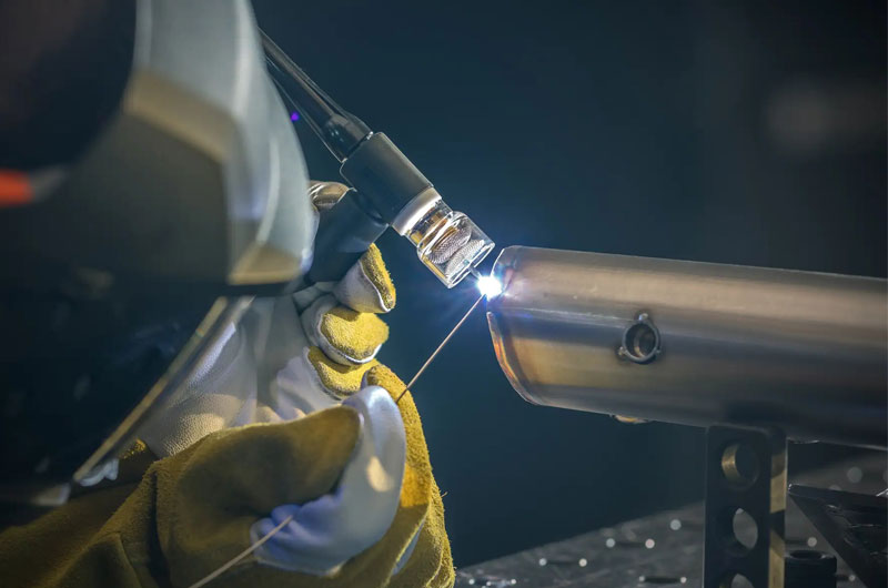
Step 5: Torch Handling and Safety
Before striking the arc, ensure you’re properly equipped and the torch is correctly positioned.
Safety Gear:
- Welding helmet with proper shade (10–13).
- TIG gloves and flame-resistant jacket.
- Fume extraction or ventilation for confined areas.
Torch Positioning:
- Hold the torch at a 10–15° angle from vertical, tilted away from the direction of travel.
- Maintain a 1/8″ or smaller gap between the tungsten and the workpiece.
- Keep your hands steady using a wrist or finger rest when possible.
Step 6: Striking the Arc
Modern TIG welders often include high-frequency (HF) start or lift-arc capabilities.
Arc Starting Methods:
- HF Start: Allows non-contact arc initiation. Ideal for aluminum.
- Lift-Arc: Touch-and-lift method. Safer for electronics-sensitive environments.
Step 7: Creating the Weld Pool
Once the arc is established, a small molten pool will form at the base metal surface. Controlling this weld pool is the key to a quality TIG weld.
Tips for Pool Formation:
- Watch for the molten metal to “wet out” the base metal evenly.
- Do not rush—move slowly and steadily.
- For butt joints, ensure fusion across both sides before adding filler.
Step 8: Adding the Filler Metal
The filler metal is usually added manually by feeding the rod into the front edge of the molten weld pool.
Key Techniques:
- Feed the rod at a consistent pace and angle (~15°–20° from the workpiece).
- Add filler at the front of the pool, not directly into the arc.
- Synchronize hand movements—torch leads slightly ahead of filler.
For autogenous welding (no filler), focus purely on fusion with no added material.
Step 9: Moving the Torch
Steady and precise torch movement ensures even bead formation and adequate fusion.
Motion Tips:
- Move the torch in a straight line or slight weave if wider coverage is needed.
- Maintain arc length—do not allow it to grow or shrink.
- Keep travel speed steady to avoid undercut or excessive heat input.
For fillet and corner welds, adjust torch angle accordingly to ensure fusion into both base materials.
Step 10: Ending the Weld
Proper arc termination is as important as the start.
Steps to Terminate:
- Gradually taper off amperage using a foot pedal or downslope feature.
- Do not abruptly stop the arc—it may cause a crater or crack.
- Hold the torch in place for post-flow gas to shield the cooling weld and tungsten.
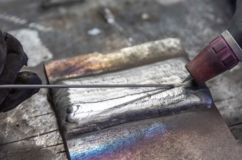
Step 11: Post-Weld Inspection and Cleanup
After welding, check your weld for quality and perform necessary finishing steps.
Inspection Criteria:
- Smooth, uniform bead with minimal spatter.
- No cracks, porosity, or undercut.
- Good penetration visible on the weld root (for open joints).
Cleaning:
- For stainless steel: Use a stainless brush or pickling paste.
- For aluminum: Minimal cleaning needed unless excessive soot is present.