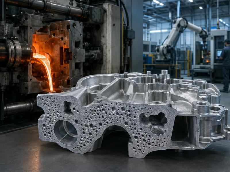
Porosity is a common die casting defect that appears as holes, voids, bubbles, or cavities inside or on the surface of a part. It may be visible after machining or found through X-ray, pressure, leakage, or destructive testing.
Porosity can reduce strength, cause leakage, affect finishing, and shorten part life, especially in demanding industries.
Common causes include trapped gas, shrinkage, poor mold design, wrong process settings, contaminated metal, moisture, and poor venting. Solving it starts with identifying the type and root cause.
What Is Porosity in Die Casting?
In die casting, molten metal is rapidly and under intense pressure pumped into a steel mould cavity. The metal fills the cavity quickly and then solidifies into the required shape. During this process, air, gas, vapor, or shrinkage cavities may become trapped inside the metal. These trapped spaces become porosity.
Porosity may appear as:
- Small round holes inside the casting
- Irregular cavities near thick sections
- Surface pinholes after polishing or coating
- Leaks in pressure-tight parts
- Voids exposed after CNC machining
- Blisters after heat treatment or plating
Small porosity may be acceptable for some non-critical parts. However, for structural parts, pressure-tight parts, electrical housings, hydraulic components, and precision-machined parts, excessive porosity can cause serious quality problems.
Principal Categories of Porosity in Die Casting
Die casting features two primary forms of porosity: gas porosity and shrinkage porosity. In many real production cases, both types may appear together.
| Type of Porosity | Main Cause | Typical Appearance | Common Location |
| Gas porosity | Air, gas, vapor, or lubricant trapped in molten metal | Smooth, round holes | Random areas, near surface, thin walls |
| Shrinkage porosity | Metal contracts during solidification without enough feeding | Irregular, rough cavities | Thick sections, hot spots, internal corners |
| Flow-related porosity | Turbulent metal flow traps air | Mixed small voids | Near gates, runners, complex features |
| Surface porosity | Gas or contamination near the surface | Pinholes or small pits | Machined or polished surfaces |
| Leakage porosity | Connected internal voids | May not be visible outside | Pressure-tight or fluid-carrying parts |
Understanding the type of porosity is the first step in finding the right solution. Gas porosity and shrinkage porosity have different causes, so they also require different corrective actions.
Air Trapped During Metal Injection
One of the biggest causes of porosity in die casting is trapped air. During the process of high-pressure die casting, the liquid metal rushes into the mold cavity at a great velocity. If the metal flow is too turbulent, it can fold over itself and trap air inside the casting.
This often happens when the gating system is poorly designed or when injection speed is too high. Instead of filling the cavity smoothly, the metal splashes, sprays, or creates waves. These unstable flow patterns capture air and form gas pockets after solidification.
Common signs of trapped air include small round holes, scattered porosity, and defects near the gate area or thin-wall sections.
How to Reduce Trapped Air
- Improve gate and runner design
- Use proper filling simulation before tooling
- Adjust injection speed and pressure
- Avoid excessive metal turbulence
- Improve venting at the end of the fill path
- Use vacuum-assisted die casting for demanding parts
Poor Mold Venting
Mold venting is critical in die casting. When molten metal fills the die cavity, the air inside the cavity must escape quickly. If the venting system is too small, blocked, poorly positioned, or not properly maintained, air remains trapped inside the metal.
Poor venting often causes gas porosity, cold shuts, incomplete filling, and surface defects. This problem is especially common in complex parts with thin walls, deep ribs, closed pockets, or long flow paths.
| Venting Problem | Possible Result |
| Vents are too small | Air cannot escape fast enough |
| Vents are in the wrong position | Gas remains trapped in dead zones |
| Vents are blocked | Increased gas porosity |
| No overflow design | Oxides and gas stay inside the casting |
| Poor die maintenance | Venting becomes worse over time |
Good venting should be considered during mold design, not only after defects appear. Overflow wells, vacuum channels, and proper parting-line vents can greatly improve casting quality.
Gas from Lubricants and Release Agents
Die casting requires lubricants and release agents to help remove the casting from the die and protect the mold surface. However, if too much lubricant is sprayed, or if it does not evaporate properly before injection, it can create gas when contacted by molten metal.
This gas may become trapped inside the casting and cause porosity. Excessive die spray can also cool the die unevenly, creating other defects such as cold shuts, flow marks, and poor surface finish.
Common Lubricant-Related Causes
- Too much release agent
- Poor spray pattern
- Uneven lubricant distribution
- Insufficient drying time
- Low die temperature after spraying
- Contaminated or incorrect lubricant
To reduce this issue, manufacturers should optimize spray volume, spray angle, air blow time, and die temperature. Automated spray systems can also improve consistency compared with manual spraying.
Moisture in Raw Material or Tooling
Moisture is another common source of gas porosity. When water or moisture contacts molten metal, it instantly turns into vapor. This vapor can create bubbles inside the casting.
Moisture may come from wet scrap, damp alloy ingots, humid storage conditions, wet ladles, or poorly dried tools. Even a small amount of moisture can cause porosity, especially in aluminum and magnesium die casting.
Common Moisture Sources
- Wet recycled metal
- Humid storage environment
- Moisture on tools or ladles
- Water-based lubricant not fully evaporated
- Condensation on cold molds
- Poor material handling
Proper drying, preheating, and storage control are important for reducing moisture-related porosity.
Hydrogen Gas in Molten Aluminum
In aluminum die casting, hydrogen gas is a major cause of porosity. Molten aluminum can absorb hydrogen from moisture, oil, furnace atmosphere, or contaminated materials. When the metal solidifies, the solubility of hydrogen diminishes, leading to the formation of gas bubbles within the casting.
Hydrogen porosity often appears as small round holes. It may become more visible after machining, polishing, or heat treatment.
How to Control Hydrogen Porosity
- Use clean and dry raw materials
- Avoid excessive remelting of scrap
- Control furnace atmosphere
- Use proper degassing methods
- Keep melting tools clean and dry
- Avoid overheating the molten metal
- Reduce contact between molten metal and moisture
Although high-pressure die casting usually has limited time for full degassing compared with other casting methods, good melting practice still helps reduce gas-related defects.
Shrinkage During Solidification
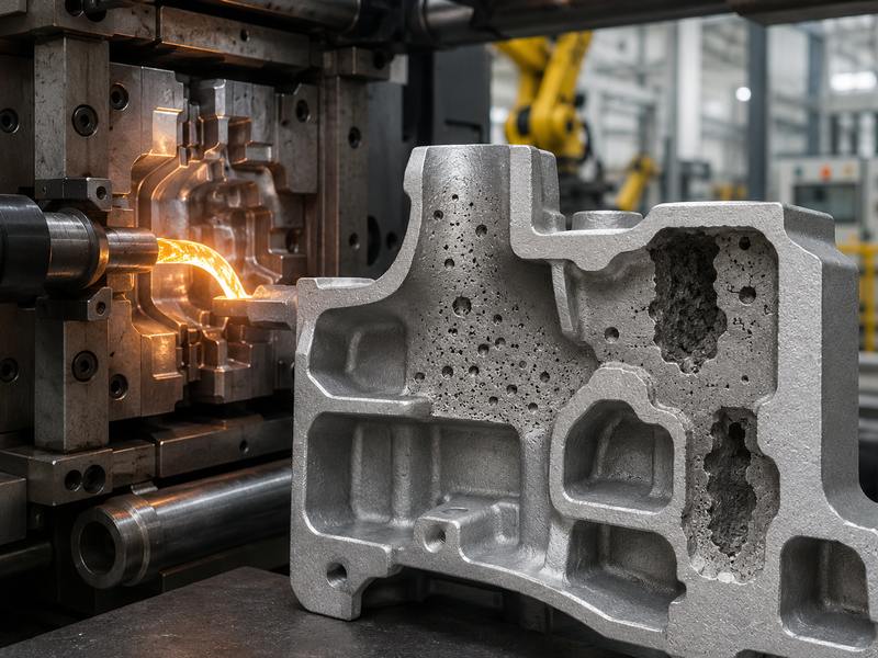
Shrinkage porosity happens because metal contracts as it cools and solidifies. If the casting design has thick sections, hot spots, or uneven wall thickness, some areas solidify later than others. When liquid metal cannot feed these areas during solidification, internal cavities form.
Shrinkage porosity usually looks more irregular and rough than gas porosity. It often appears in thick sections, bosses, ribs, intersections, and heavy walls.
| Design Feature | Porosity Risk |
| Thick walls | High shrinkage risk |
| Sudden wall thickness changes | Hot spots and uneven cooling |
| Large bosses | Internal voids |
| Heavy ribs | Localized shrinkage |
| Poor radius design | Stress and solidification issues |
| Deep blind pockets | Trapped air and poor filling |
Good part design is essential for reducing shrinkage porosity. Uniform wall thickness, proper radii, optimized ribs, and correct gate position can help the metal solidify more evenly.
Subpar Design of Gates and Runners
The gating system regulates the entry of molten metal into the die cavity. If the gate and runner design is poor, the metal may fill the mold unevenly, trap air, create turbulence, or solidify too early.
A gate that is undersized can lead to high-speed jetting and turbulence. A gate that is too large may create poor pressure control and longer solidification time. Incorrect gate location may force metal to flow around complex features, trapping air in blind areas.
Gate Design Problems That Cause Porosity
- Gate placed in the wrong position
- Runner too long or too narrow
- Unbalanced multi-cavity filling
- Sharp turns in the runner system
- Poor overflow placement
- Excessive injection speed through small gates
- Metal flow path too long or too complex
Die casting simulation can help predict flow behavior, air entrapment, and temperature distribution before mold manufacturing.
Incorrect Injection Speed and Pressure
Injection speed and pressure directly affect porosity. If injection speed is too slow, the metal may cool before filling the cavity, causing cold shuts and incomplete filling. If injection speed is too fast, turbulence and air entrapment may increase.
Pressure is also important. Insufficient intensification pressure may fail to compact the metal properly during solidification. This can lead to shrinkage porosity and poor density.
| Process Parameter | Too Low | Too High |
| Injection speed | Cold shuts, incomplete filling | Turbulence, air entrapment |
| Injection pressure | Poor compaction, shrinkage | Flash, die wear, turbulence |
| Metal temperature | Poor flow, cold shuts | More gas pickup, die damage |
| Die temperature | Poor filling, cold defects | Longer solidification, shrinkage |
Stable process control is important. Modern die casting machines often monitor shot speed, pressure curve, fill time, and intensification pressure to improve repeatability.
Improper Metal Temperature
Metal temperature has a major effect on porosity. If molten metal is too cold, it may not flow smoothly into thin sections, causing cold shuts and flow-related defects. If the metal is too hot, it may absorb more gas, increase die soldering, damage the die, and create more shrinkage risk.
The correct pouring or injection temperature depends on the alloy, part geometry, wall thickness, and die design. Manufacturers should avoid guessing and instead use controlled process windows.
For copper die casting, temperature control is even more critical because copper alloys have higher melting points than aluminum and zinc. Poor temperature control can quickly lead to die wear, poor filling, or internal defects.
Poor Die Temperature Control
The temperature must be stable and balanced. If some areas of the die are too cold, the metal may freeze too early. If some areas are too hot, shrinkage porosity may develop in those hot spots.
In regions characterized by wall thickness variability or intricate geometrical structures, temperature imbalance frequently occurs. Without proper cooling channels, thermal pins, or die temperature control systems, some sections may solidify much later than others.
Die Temperature Control Methods
- Cooling channels
- Thermal pins
- Die temperature controllers
- Infrared temperature monitoring
- Balanced spray cooling
- Regular mold maintenance
- Mold temperature mapping
Good die thermal balance helps reduce both gas porosity and shrinkage porosity.
Contaminated Metal
Contaminated metal can also cause porosity. Oxides, slag, dirt, oil, paint, and other impurities may enter the melt and become trapped inside the casting. Recycled scrap can reduce cost, but it must be clean and controlled.
Contamination may also create inclusions, weak areas, poor surface finish, and machining problems. In severe cases, contaminants can block flow channels or create internal leakage paths.
Common Contamination Sources
- Dirty scrap metal
- Oxide films
- Slag from melting
- Oil or paint on recycled material
- Poor furnace cleaning
- Incorrect alloy mixing
- Poor skimming practice
Metal cleanliness should be controlled through proper material sorting, melting practice, skimming, filtration, and furnace maintenance.
Poor Part Design
Even with a good machine and good mold, poor part design can still cause porosity. Die casting works best when the part has uniform wall thickness, smooth transitions, proper draft angles, and well-designed ribs and bosses.
Parts with thick sections, deep pockets, isolated heavy areas, or sharp internal corners are more likely to develop shrinkage porosity and trapped gas.
Design Tips to Reduce Porosity
- Keep wall thickness as uniform as possible
- Avoid large isolated thick sections
- Use ribs instead of solid heavy walls
- Add smooth radii at corners
- Avoid deep blind pockets
- Design for smooth metal flow
- Consider machining allowance carefully
- Avoid placing critical machining surfaces in high-risk porosity areas
Design for manufacturability should be done before mold production. Once the die is built, solving porosity becomes more expensive.
How to Identify the Cause of Porosity
Finding porosity is easy, but finding the real cause requires analysis. The same part may have several possible causes, so manufacturers should combine inspection data with process records.
| Inspection Method | What It Helps Identify |
| Visual inspection | Surface pinholes and exposed porosity |
| CNC machining check | Internal porosity near machined surfaces |
| X-ray inspection | Hidden internal voids |
| Pressure testing | Leakage caused by connected porosity |
| Section cutting | Porosity shape and location |
| Process data review | Speed, pressure, temperature variation |
| Mold flow simulation | Air entrapment and hot spot prediction |
| Metallographic analysis | Gas holes, shrinkage, inclusions, and micro defects |
A round and smooth cavity usually suggests gas porosity. An irregular and rough cavity often suggests shrinkage porosity. Porosity near the surface may be related to trapped gas or lubricant. Porosity in thick sections is more likely related to shrinkage.
Practical Solutions for Reducing Porosity
Porosity cannot always be completely eliminated, but it can be controlled and reduced through better design, tooling, process control, and inspection.
Effective Strategies for Reducing Porosity
- Optimize the design of parts to ensure uniform wall thickness
- Improve gate and runner design
- Add proper vents and overflow channels
- Utilize vacuum die casting for essential components
- Control injection speed and pressure
- Maintain stable metal temperature
- Balance die temperature
- Reduce excessive release agent
- Keep raw materials clean and dry
- Use X-ray or pressure testing for critical parts
- Improve mold maintenance and vent cleaning
- Use simulation before tooling production
Porosity Troubleshooting Table
| Problem Found | Possible Cause | Recommended Action |
| Small round holes | Trapped air or gas | Improve venting, reduce turbulence, check lubricant |
| Irregular internal cavities | Shrinkage | Improve feeding, reduce hot spots, adjust gate design |
| Pinholes after polishing | Surface gas porosity | Improve die spray, venting, and metal cleanliness |
| Leakage during pressure test | Connected porosity | Use vacuum casting, improve compaction pressure |
| Porosity near thick areas | Solidification shrinkage | Modify part design or cooling system |
| Porosity near gate | Turbulent filling | Adjust gate size, speed, and runner design |
| Blisters after plating | Gas trapped near surface | Improve cleaning, degassing, and casting parameters |
| Porosity after machining | Internal voids exposed | Adjust machining allowance and casting process |
Can Porosity Be Completely Eliminated?
In many die-cast parts, very small internal porosity may be difficult to eliminate completely because high-pressure die casting is a fast process. However, porosity can be controlled to meet functional requirements.
For non-critical decorative parts, small internal porosity may be acceptable if it does not affect appearance or machining. For pressure-tight parts, structural parts, electrical housings, and safety-related components, stricter control is necessary.
The key is to define quality standards clearly before production. It is important for buyers to detail their tolerance specifications, leakage requirements, machining areas, surface finishing needs, and inspection standards.
Why Porosity Control Matters for Buyers
For buyers, porosity control is important because it directly affects product performance and long-term reliability. A part may look good on the outside but still contain internal defects. If porosity appears after machining or during assembly, it can increase scrap cost, delay delivery, and cause customer complaints.
Buyers should discuss porosity requirements with the supplier before mold design. Important details include:
- Part application
- Pressure or leakage requirements
- Machined surfaces
- Surface finishing requirements
- Mechanical strength requirements
- Testing standards
- Annual order quantity
- Material grade
- Assembly conditions
A reliable die casting manufacturer should not only produce parts, but also provide design advice, mold optimization, process control, inspection, and improvement solutions.
Die casting porosity is mainly caused by trapped gas, poor venting, shrinkage, wrong process settings, contaminated metal, moisture, unstable die temperature, or poor part design.
Reducing porosity requires proper design, mold structure, material control, die temperature, injection speed, pressure, venting, and inspection. For complex parts, simulation, vacuum die casting, X-ray testing, and process monitoring help improve quality.