Aluminum block machining is widely used in CNC milling due to its lightweight strength, corrosion resistance, and excellent machinability. This guide covers material selection, design, tooling, machining strategies, and common challenges.
What Is Aluminum Block Machining?
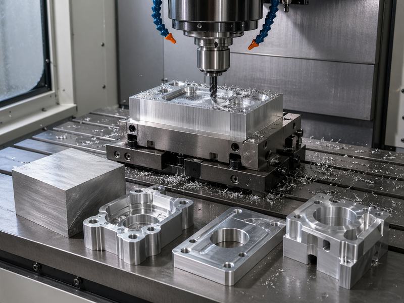
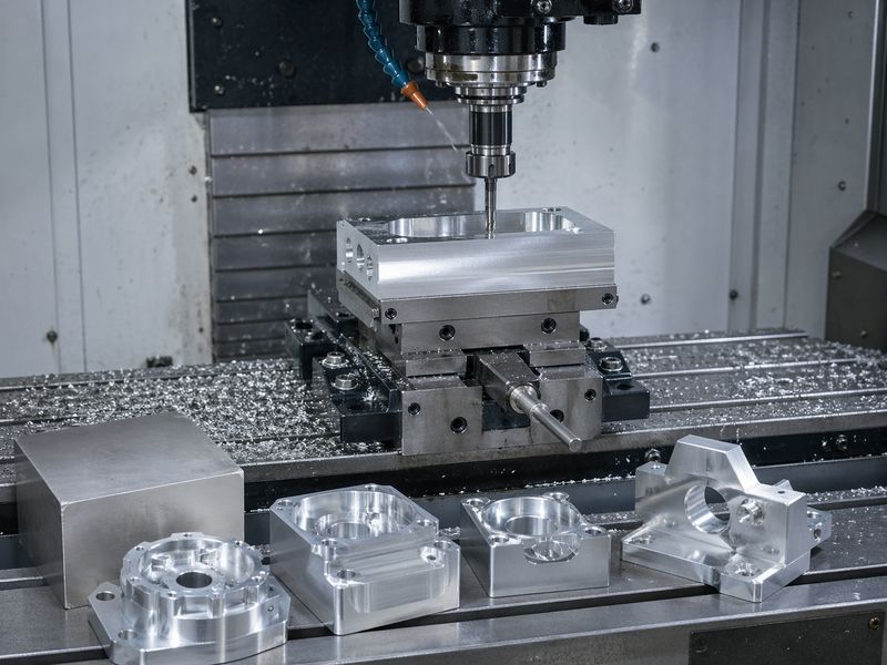
Aluminum block machining refers to the process of removing material from a solid aluminum workpiece (block) to create a finished part with specific geometry and tolerances. This is typically done using CNC milling machines, which employ rotating cutting tools to carve material precisely according to programmed instructions.
Unlike additive manufacturing, CNC machining is a subtractive process, meaning excess material is removed layer by layer until the desired shape is achieved.
Key Characteristics
- High precision and repeatability
- Ability to create complex geometries
- Excellent surface finish
- Suitable for both prototyping and mass production
Because aluminum is relatively soft compared to steel, it can be machined 3–4 times faster, reducing cycle time and manufacturing costs.
Why Aluminum Is Ideal for CNC Milling
Aluminum’s balanced mechanical and physical qualities set it apart from other machining materials.
Core Advantages
- Excellent Machinability
Aluminum requires less cutting force, enabling faster machining and reduced tool wear.
- Lightweight but Robust
It is substantially lighter than steel and offers strong structural strength.
- Resistance to Corrosion
Reduces the need for coatings by naturally forming a protective oxide layer.
- Thermal Conductivity
Helps dissipate heat during machining, improving tool life and surface finish.
- Adaptability
Accessible in a variety of alloys appropriate for various uses.
Typical CNC Milling Aluminum Alloys
| Alloy | Key Features | Typical Applications |
| 6061-T6 | Good strength, corrosion resistance, easy machining | General engineering parts |
| 7075-T6 | High strength, aerospace-grade | Aircraft components |
| 2024 | Excellent fatigue resistance | Structural parts |
| 5052 | Good formability, corrosion resistance | Marine and sheet components |
CNC Milling Process for Aluminum Blocks
The CNC milling workflow involves several critical stages:
Step 1: CAD Design
Engineers create a 3D model using CAD software. This defines geometry, tolerances, and material specifications.
Step 2: CAM Programming
The CAD model is converted into toolpaths using CAM software. The CNC machine is guided by these instructions.
Step 3: Get the Supplies Ready
The aluminum block is cut to approximate size and securely clamped using fixtures or vises.
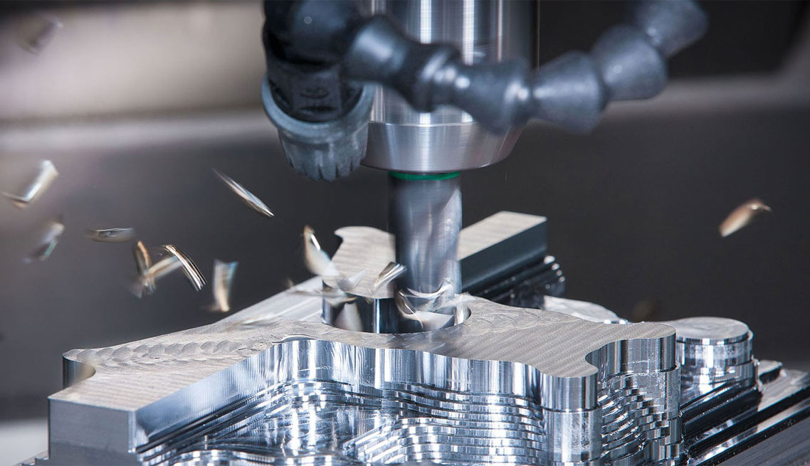
Step 4: Roughing
Bulk material is removed quickly using aggressive cutting parameters.
Step 5: Semi-Finishing
Refines geometry and prepares surfaces for finishing.
Step 6: Finishing
Final passes achieve tight tolerances and smooth surface finishes.
Step 7: Post-Processing
Includes:
- Deburring
- Anodizing
- Polishing
- Sandblasting
Tooling for Aluminum CNC Milling
Selecting the right cutting tools is essential for efficient machining.
Materials for Tools
- Carbide tools: Preferred for high-speed machining and durability
- High-speed steel (HSS): Suitable for low-volume or softer alloys
Carbide tools are widely used because they maintain sharp edges and withstand higher temperatures, improving performance in aluminum machining.
Tool Geometry
- 2-flute end mills: Best for chip evacuation
- 3-flute end mills: Balance between strength and speed
- High-helix cutters: Improve chip removal and surface finish
Proper chip evacuation is critical, as aluminum chips can weld to the tool and degrade performance.
Cutting Parameters Include Depth, Feeds, and Speeds.
Achieving high-quality outcomes requires optimizing cutting parameters.
Key Parameters
| Parameter | Description | Optimization Tip |
| Spindle Speed | Rotation speed of tool | Use higher speeds for aluminum |
| Feed Rate | Tool movement speed | Maintain consistent feed to avoid rubbing |
| Depth of Cut | Material removed per pass | Use deeper cuts during roughing |
| Chip Load | Material removed per tooth | Adjust based on tool size |
Aluminum prefers higher spindle speeds and consistent feed rates to produce clean chips and prevent tool wear.
Design Guidelines for Aluminum CNC Milling
Good design improves manufacturability and reduces cost.
Best Practices
- Avoid Thin Walls
Thin sections can vibrate and reduce accuracy. - Use Standard Tool Sizes
Reduces machining time and tooling costs. - Minimize Tight Tolerances
Only apply tight tolerances where necessary to reduce cost. - Avoid Sharp Internal Corners
Use fillets to match tool geometry. - Optimize Pocket Depth
Deep pockets increase machining difficulty and tool deflection.
Common Challenges in Aluminum Machining
Despite its advantages, aluminum machining presents several challenges.
Chip Adhesion (Built-Up Edge)
Aluminum chips can stick to cutting tools, causing poor surface finish.
Solution:
- Use sharp tools
- Apply coolant or air blast
- Maintain proper speeds
Heat Generation
Although aluminum dissipates heat well, improper parameters can cause melting.
Solution:
- Use coolant
- Optimize cutting speeds
- Ensure proper chip evacuation
Vibration (Chatter)
High-speed machining may cause instability.
Solution:
- Increase machine rigidity
- Adjust feed and speed
- Use proper workholding
Warping
Soft aluminum may deform during machining.
Solution:
- Use stress-relieved materials (e.g., T651)
- Apply balanced machining strategies
Workholding Techniques
Secure workholding is critical for precision.
Common Methods
- Vise clamping– Most common for blocks
- Vacuum tables– Ideal for thin parts
- Custom fixtures– Used for complex geometries
Rigid setups allow for more aggressive cutting and improved accuracy.
Surface Finishing Options
Aluminum parts often require post-processing to enhance performance and aesthetics.
Common Finishes
| Process | Purpose | Result |
| Anodizing | Corrosion resistance | Durable oxide layer |
| Polishing | Aesthetic improvement | Smooth, shiny surface |
| Sandblasting | Texture control | Matte finish |
| Powder Coating | Protection | Colored, durable coating |
Applications of Aluminum CNC Milling
In many industries, aluminum block machining is utilized:
Aerospace
- Structural brackets
- Engine components
- Lightweight frames
Automotive
- Engine blocks
- Transmission housings
- Suspension parts
Electronics
- Heat sinks
- Device enclosures
- Laptop and smartphone frames
Industrial Equipment
- Machine components
- Robotics parts
- Automation systems
Aluminum’s versatility allows manufacturers to produce both functional and aesthetic components efficiently.
Cost Considerations in Aluminum CNC Projects
Several factors influence machining cost:
Key Cost Drivers
- Material grade and size
- Machining time
- Tool wear
- Complexity of geometry
- Surface finish requirements
Cost Optimization Tips
- Simplify design
- Use standard tolerances
- Reduce material waste
- Optimize toolpaths
Because aluminum machines quickly, it often results in lower overall production costs compared to harder metals like steel.
Best Practices for Successful Projects
To ensure successful aluminum CNC milling projects:
Practical Tips
- Use sharp, high-quality tools
- Maintain proper chip evacuation
- Optimize feeds and speeds
- Ensure machine rigidity
- Select the correct alloy and temper
Understanding material behavior and machining dynamics is essential for achieving consistent, high-quality results.
Aluminum block machining is essential in CNC milling, offering high efficiency, precision, and cost-effective production of complex parts. By optimizing material choice, tooling, and parameters, manufacturers can maximize performance across industries, and it will remain vital as CNC technology advances.