Porosity in aluminum die casting is caused by gas entrapment, hydrogen, shrinkage, poor venting, mold design issues, unstable parameters, and poor melt control. Since these factors are often connected, reducing porosity requires full process control, including part and mold design, venting, molten aluminum quality, injection settings, mold temperature, lubrication, maintenance, and inspection. Effective porosity control helps produce stronger parts, better sealing, improved machining quality, lower scrap rates, and more stable mass production.
What Does Porosity Mean in Aluminum Die Casting?
Porosity refers to small internal or surface voids formed during the die casting process. These voids are usually caused by trapped gas, air, shrinkage during solidification, or improper metal flow.
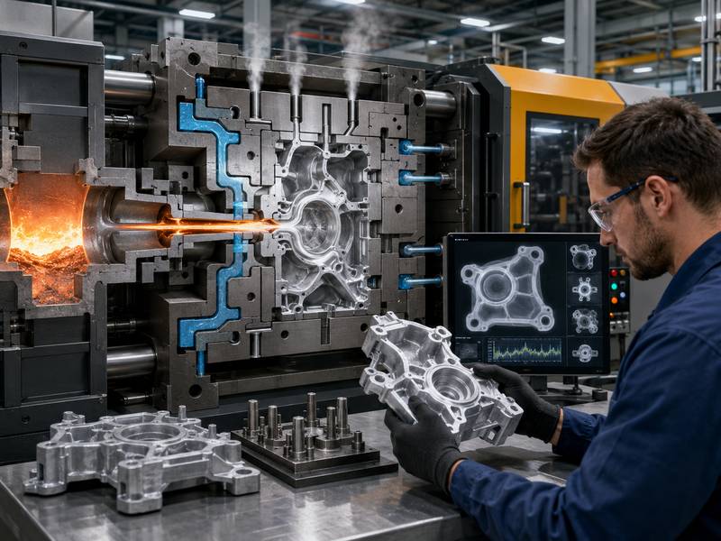
In the process of aluminum die casting, a steel mold cavity is filled with molten aluminum at high velocity and under high pressure. Because the process is fast, air and gas may become trapped inside the molten metal. At the same time, aluminum shrinks as it cools and solidifies. If feeding and solidification are not well controlled, shrinkage cavities may form.
There are two primary categories of porosity: gas porosity and shrinkage porosity.
| Type of Porosity | Main Cause | Common Appearance | Typical Risk |
| Gas Porosity | Trapped air, hydrogen gas, poor venting | Round or smooth holes | Leakage, weak structure, poor machining |
| Shrinkage Porosity | Metal shrinkage during solidification | Irregular cavities | Reduced strength, cracking risk |
| Surface Porosity | Gas or shrinkage near the surface | Small pits or pinholes | Poor coating, plating, painting, or anodizing |
| Machining-Exposed Porosity | Internal pores opened during machining | Holes appear after CNC machining | Scrap, leakage, customer rejection |
Understanding the type of porosity is the first step toward solving the problem. Gas porosity usually requires better venting, vacuum support, melt treatment, and injection control. Shrinkage porosity usually requires better part design, gate design, cooling control, and solidification management.
Why Porosity Matters
Some small pores may not affect simple decorative parts, but for functional aluminum die casting parts, porosity can become a serious problem.
Porosity can reduce mechanical strength because voids interrupt the metal structure. It can also create leakage paths in parts used for housings, pump bodies, valve bodies, air-tight covers, and fluid control components. During CNC machining, hidden porosity may be exposed, causing visible defects on sealing surfaces, threaded holes, or precision areas.
Porosity can also affect surface treatment. Parts with surface pores may show bubbles, pits, stains, or coating failure after painting, powder coating, plating, or anodizing.
For high-performance applications, customers often set strict requirements for porosity level, X-ray inspection, pressure testing, or machining surface quality. Therefore, porosity control should be considered from the beginning of product design, not only after casting defects appear.
Principal Reasons for Aluminium Die Casting Porosity
Porosity is usually caused by multiple factors working together. A part may have porosity because of poor mold venting, improper injection speed, high melt temperature, contaminated aluminum, unsuitable wall thickness, or poor cooling balance.
1. Trapped Air During Filling
High-pressure die casting fills the mold cavity very quickly. If the metal flow is turbulent, air can be trapped inside the molten aluminum. When the metal solidifies, trapped air becomes internal pores.
This problem is common when the gate design is poor, the filling path is too complex, or the air cannot escape through vents and overflows.
2. Hydrogen Gas in Molten Aluminum
Aluminum can absorb hydrogen when it is molten. Moisture from tools, furnace atmosphere, lubricants, or recycled material can increase hydrogen content. As the aluminum cools, hydrogen solubility decreases, and gas bubbles may form inside the casting.
3. Poor Venting and Overflow Design
Air will stay trapped in the cavity if the mould prevents air from escaping. Insufficient venting, blocked vents, small overflow areas, or poor vacuum design can all increase porosity.
4. Shrinkage During Solidification
Aluminum contracts as it cools. If thick sections solidify last without enough metal feeding, shrinkage porosity may appear. Parts with varied wall thickness, thick bosses, abrupt transitions, or isolated heavy areas are particularly prone to this.
5. Improper Die Casting Parameters
Injection speed, pressure, temperature, and cooling time all affect porosity. If the first-stage speed is too high, air may be trapped before the cavity is properly filled. If the second-stage speed is too aggressive, turbulence may increase. If pressure is insufficient, the metal may not be compacted properly.
6. Poor Mold Temperature Control
If mold temperature is too low, the metal may solidify too early, causing cold shuts and flow problems. If mold temperature is too high, solidification may slow down and increase shrinkage defects. Uneven mold temperature can also create unstable filling and solidification.
Practical Ways to Reduce Porosity
Reducing porosity requires control across the whole process. The most effective approach is to combine good part design, proper alloy handling, optimized mold design, stable process parameters, and strict inspection.
Optimize Part Design
Good casting quality starts with good part design. If the part structure is not suitable for die casting, process adjustments alone may not fully solve porosity problems.
The walls should be as uniform as possible in thickness. Large differences between thin and thick areas can cause uneven cooling and shrinkage porosity. Heavy bosses, thick ribs, and deep pockets should be avoided or redesigned.
Sharp corners should be replaced with proper radii. Smooth transitions help molten aluminum flow more evenly and reduce turbulence. Ribs should be designed with suitable thickness to improve strength without creating heavy metal accumulation.
| Design Factor | Poor Design Risk | Recommended Improvement |
| Uneven wall thickness | Shrinkage porosity, hot spots | Keep wall thickness uniform |
| Thick bosses | Internal shrinkage cavities | Use hollow bosses or reduce mass |
| Sharp corners | Turbulent flow, stress concentration | Add proper fillets and radii |
| Long thin sections | Cold shuts, incomplete filling | Improve flow path and gate location |
| Isolated heavy areas | Late solidification | Add ribs, reduce thickness, or improve cooling |
A casting engineer should review the part design before tooling. Design for manufacturability can prevent many porosity problems before production begins.
Improve Gate and Runner Design
The gating system controls how molten aluminum enters the mold cavity. Poor gate and runner design can cause turbulence, air entrapment, uneven filling, and local shrinkage.
A good gate design should allow smooth, directional, and balanced filling. The metal should push air toward vents and overflows instead of trapping it inside the cavity. Gate location should be selected based on part geometry, wall thickness, flow distance, and critical quality areas.
For parts requiring machining, sealing, or pressure tightness, gates should be designed to reduce porosity near functional surfaces. Simulation software can help predict air entrapment, flow behavior, temperature distribution, and shrinkage risk before mold manufacturing.
Enhance Venting and Overflow Design
Venting is one of the most important factors in reducing gas porosity. During filling, air inside the cavity must escape quickly. If venting is not enough, air becomes trapped and forms pores.
Vents should be placed at the last filling areas, flow ends, and locations where air is likely to collect. Overflows can help collect cold metal, oxides, and trapped gas. They also improve filling stability.
For high-quality aluminum die casting parts, vacuum die casting can be used to remove air from the cavity before and during injection. Vacuum systems are especially useful for structural parts, pressure-tight parts, and components with strict porosity requirements.
| Method | Function | Benefit |
| Proper vent placement | Allows air to escape | Reduces gas porosity |
| Overflow wells | Collect cold metal and trapped air | Improves filling quality |
| Vacuum system | Removes air from cavity | Reduces internal pores |
| Regular vent cleaning | Prevents blockage | Keeps process stable |
| Flow simulation | Predicts trapped air areas | Improves mold design before trial |
Vents and overflows should be maintained regularly. Lubricant residue, aluminum flash, and dirt can block venting channels and increase porosity over time.
Control Molten Aluminum Quality
Molten aluminum quality has a direct influence on porosity. Contaminated metal, high gas content, excessive oxides, or wet charge materials can increase defects.
The aluminum should be properly melted, cleaned, degassed, and protected. Recycled material should be controlled carefully because it may contain oil, moisture, coatings, or impurities. Tools and ladles should be dry before contacting molten aluminum.
Degassing is commonly used to reduce hydrogen content in molten aluminum. Fluxing and skimming can help remove oxides and inclusions. Holding temperature should also be controlled to avoid excessive gas absorption and oxidation.
Good melt management includes:
- Keeping charge materials dry and clean.
- Avoiding excessive turbulence during metal transfer.
- Removing slag and oxides before casting.
- Using proper degassing methods.
- Controlling furnace and holding temperature.
- Avoiding long holding times when possible.
Stable molten metal quality helps reduce both gas porosity and inclusion-related defects.
Optimize Injection Parameters
Die casting machine parameters must be carefully adjusted according to part size, wall thickness, alloy type, mold design, and quality requirements.
The filling process usually includes a slow shot stage and a fast shot stage. The slow shot stage helps push air out of the shot sleeve smoothly. If it is too fast, air may be trapped in the metal before injection. Although the fast shot stage quickly fills the mould cavity, too much speed may result in turbulence.
Intensification pressure is also important. Proper pressure helps compact the metal during solidification and reduce small voids. However, pressure alone cannot solve porosity if air is already trapped in the cavity.
| Process Parameter | If Too Low | If Too High | Control Goal |
| Melt temperature | Cold shuts, poor filling | More gas absorption, shrinkage risk | Stable filling and solidification |
| Mold temperature | Early freezing, flow marks | Slow cooling, shrinkage risk | Balanced heat control |
| Slow shot speed | Poor metal movement | Air entrapment in shot sleeve | Smooth metal advance |
| Fast shot speed | Incomplete filling | Turbulence, trapped air | Fast but controlled filling |
| Intensification pressure | Loose structure, voids | Flash, mold stress | Compact metal properly |
| Cooling time | Deformation, hot part | Low productivity | Complete solidification |
Process settings should not be adjusted randomly. It is better to use trial data, defect location analysis, and simulation results to make controlled improvements.
Maintain Proper Mold Temperature
Mold temperature affects metal flow, solidification, and final part quality. A mold that is too cold may cause the aluminum to freeze before the cavity is fully filled. A mold that is too hot may slow solidification and increase shrinkage porosity.
Temperature balance is also important. If one area of the mold is much hotter than another, the part may solidify unevenly. This can create hot spots and shrinkage cavities.
Cooling channels, spot cooling, thermal pins, and mold temperature controllers can help manage heat. For thick sections, additional cooling may be needed to reduce local hot spots. For thin areas, proper preheating and temperature control can improve filling.
Thermal imaging and mold temperature monitoring can help identify unstable temperature zones during production.
Reduce Lubricant and Moisture Problems
Die release agents are necessary for part release and mold protection, but excessive lubricant can cause gas generation. If lubricant accumulates in the cavity, it may vaporize during injection and increase porosity.
The spray amount, spray position, spray time, dilution ratio, and air blow-off should be controlled. The mold surface should be dry before injection. Water-based release agents must be managed carefully because moisture can quickly turn into steam when it contacts molten aluminum.
To reduce lubricant-related porosity, manufacturers should:
- Use the correct dilution ratio.
- Avoid over-spraying.
- Improve spray automation.
- Ensure proper air blow-off.
- Prevent lubricant buildup in deep areas.
- Keep the mold surface dry before casting.
A stable and repeatable spray process is better than manual adjustment based only on operator experience.
Use Die Casting Simulation
Simulation is a powerful tool for reducing porosity before mold manufacturing and during process improvement. It can predict filling behavior, air entrapment, temperature distribution, solidification sequence, and shrinkage risk.
With simulation, engineers can test different gate locations, runner sizes, vent positions, overflow designs, and cooling layouts before cutting steel. This cuts down on trial-and-error expenses and development time.
For existing molds, simulation can also help explain why porosity appears in certain areas. Engineers can compare defect locations with predicted air traps or hot spots, then improve the mold or process accordingly.
Improve Tooling Maintenance
Even a well-designed mold can develop porosity problems if it is not maintained properly. Vent channels may become blocked. Cooling channels may lose efficiency. Ejector pins may wear. Flash may affect mold sealing. Surface damage may change metal flow.
Regular mold maintenance should include checking vents, overflows, sliders, cooling lines, gate wear, parting surfaces, and vacuum channels. Blocked vents are a common reason why a stable process suddenly starts producing porous parts.
Tooling maintenance should be recorded, and critical mold areas should be inspected after a defined number of shots.
Inspect and Analyze Porosity Correctly
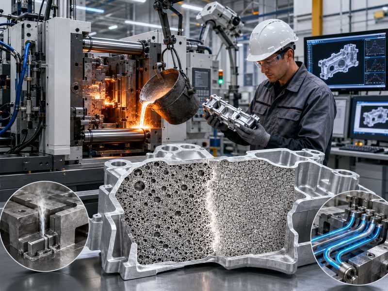
Porosity reduction depends on accurate inspection and root cause analysis. Depending on the requirements of the part, various inspection techniques might be applied.
X-ray inspection is useful for checking internal porosity without cutting the part. Sectioning can reveal pore shape and location. Pressure testing is important for leak-tight parts. CNC machining inspection can show whether internal pores appear on functional surfaces.
| Inspection Method | Best For | Advantage | Limitation |
| Visual inspection | Surface defects | Fast and simple | Cannot find internal porosity |
| X-ray inspection | Internal pores | Non-destructive | Higher cost |
| Section cutting | Root cause analysis | Shows pore shape clearly | Destroys sample |
| Pressure testing | Leak-tight parts | Confirms sealing performance | Does not show exact pore source |
| Machining inspection | Functional surfaces | Finds exposed porosity | Defect appears after value-added process |
The shape of pores can help identify the cause. Round, smooth pores often indicate gas porosity. Irregular, interconnected cavities usually suggest shrinkage porosity. This distinction helps engineers choose the right corrective action.
Common Mistakes to Avoid
Many porosity problems continue because manufacturers only adjust machine parameters without solving the real cause. For example, increasing pressure may not help if the mold has poor venting. Lowering temperature may not help if shrinkage is caused by thick wall design. Adding more cooling may not solve gas porosity caused by wet material or excessive lubricant.
Focusing just on obvious flaws is another frequent error. Internal porosity may not be seen until machining, pressure testing, or customer assembly. For critical parts, inspection should be included early in the production plan.
It is also important not to ignore process consistency. A part may pass during mold trial but fail during mass production if temperature, spray, metal quality, and cycle time are not controlled.
Best Practice Checklist for Reducing Porosity
A complete porosity reduction strategy should include the following points:
- Review part design for uniform wall thickness and smooth transitions.
- Optimize gate, runner, vent, and overflow design.
- Use vacuum die casting for demanding applications.
- Control molten aluminum cleanliness and hydrogen content.
- Keep charge materials, tools, and ladles dry.
- Set stable injection speed, pressure, temperature, and cooling time.
- Maintain balanced mold temperature.
- Avoid excessive release agent and moisture.
- Clean vents and overflows regularly.
- Use X-ray, sectioning, and pressure testing for root cause analysis.
Manufacturers can greatly reduce porosity and increase casting dependability by combining these techniques.