
Standard CNC machining tolerances for most commercial metals sit at ±0.125 mm (±0.005 inches). However, the absolute tightest achievable limits depend heavily on the material being cut. Aluminum and carbon steel can reliably hold ±0.025 mm (±0.001 in) on standard setups due to predictable machinability. Stainless steel usually caps between ±0.025 mm and ±0.05 mm because it work-hardens under the cutter. Titanium typically maxes out at ±0.05 mm (±0.002 in) in standard milling because its low thermal conductivity traps heat, causing tool deflection and elastic springback that destroy tight dimensional controls.
Specifying a ±0.010 mm limit on an engineering drawing doesn’t mean the machine shop can automatically achieve it. On the shop floor, metal properties physically dictate how a part reacts to the stress of a cutting tool.
The Physics Behind Dimensional Drift
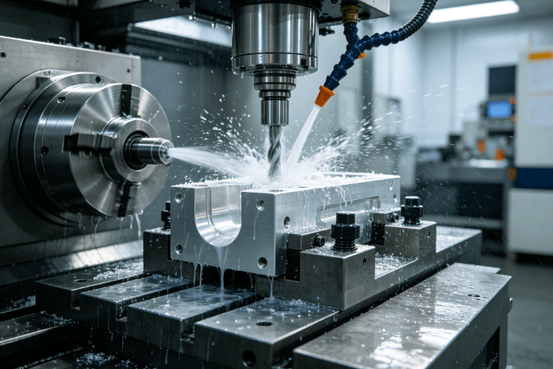
Engineers often assume that CNC precision is solely a function of machine quality. While rigid spindles and high-resolution encoders matter, the metal itself fights back during the machining process. Three physical variables control whether a dimension stays in spec across a production run.
Thermal Expansion
Cutting metal generates extreme friction. Metals with high thermal conductivity pull this heat away. Metals with poor conductivity trap it. If a part heats up significantly during heavy roughing passes, it expands. An operator might measure the hot part inside the machine and see it perfectly on nominal. Once that part hits the inspection room and cools to 20°C (68°F), it shrinks entirely out of tolerance.
Tool Deflection
Harder alloys require higher cutting forces. This force pushes the cutter away from the workpiece. Even a microscopic bend in a solid carbide endmill means the tool cuts a slightly shallower path than programmed, leaving the part oversized.
Work Hardening
Certain alloys change their metallurgical structure when subjected to mechanical stress. If a cutting tool dwells, rubs, or uses an incorrect feed rate, the surface of the metal hardens instantly. The next tool pass hits this hardened layer, deflecting the cutter and ruining the dimensional accuracy.
Precision Limits: Evaluating the Core Four Metals
Different alloys require entirely distinct manufacturing strategies, tooling geometries, and coolant setups to hold precision.
Aluminum Alloys (6061-T6, 7075)
Aluminum is the benchmark for easy machinability. Its softness reduces cutting forces, meaning tool deflection is minimal even at high feed rates.
-
Standard Tolerance: ±0.125 mm (±0.005 in)
-
Tightest Practical Limit: ±0.025 mm (±0.001 in)
-
Shop Floor Reality: The primary enemy of aluminum precision is heat. Its coefficient of thermal expansion is roughly double that of steel. High-volume production requires aggressive flood coolant to keep the part at a stable temperature. Thin-walled aluminum features are also prone to vibration (chatter), which can throw off critical dimensions.
Carbon and Alloy Steels (1018, 4140)
Steel behaves predictably. It does not expand rapidly with heat, and it does not typically work-harden aggressively.
-
Standard Tolerance: ±0.125 mm (±0.005 in)
-
Tightest Practical Limit: ±0.025 mm (±0.001 in)
-
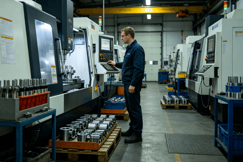
Shop Floor Reality: The challenge with tougher alloys like 4140 is tool wear. As a batch of 500 parts runs, the cutting edges slowly degrade. A dull tool pushes harder against the metal, causing dimensions to drift. Machine operators must continuously monitor limits and input tool wear offsets into the CNC controller to maintain a ±0.001 in tolerance across the entire batch.
Stainless Steel (304, 316L)
Austenitic stainless steels are highly resistant to corrosion due to their chromium and nickel content, making them a staple in medical and food-grade applications.
-
Standard Tolerance: ±0.125 mm (±0.005 in)
-
Tightest Practical Limit: ±0.050 mm (±0.002 in)
-
Shop Floor Reality: Stainless steel is infamous for work hardening. Machinists must maintain a heavy, continuous chip load. If a tool pecks at the material or loses its sharp edge, the surface hardens immediately. Achieving tighter than ±0.050 mm often requires secondary grinding operations, which drastically increases part costs.
Titanium (Ti-6Al-4V / Grade 5)
Titanium boasts an incredible strength-to-weight ratio but is notoriously hostile to cutting tools.
-
Standard Tolerance: ±0.125 mm (±0.005 in)
-
Tightest Practical Limit: ±0.050 mm (±0.002 in)
-
Shop Floor Reality: Titanium acts like a thermal insulator. The heat generated during cutting does not enter the chip; it stays on the cutting edge, destroying the tool rapidly. Furthermore, titanium has a low modulus of elasticity—meaning it bends and “springs back” away from the cutter. Holding strict tolerances requires highly rigid machine setups, specialized tool paths (like trochoidal milling), and high-pressure through-spindle coolant.
Material Tolerance Capability Matrix
| Material Grade | Thermal Expansion Risk | Work Hardening Risk | Practical CNC Limit | Primary Machining Challenge |
| Aluminum (6061) | High | Low | ±0.025 mm | Thermal growth, thin-wall vibration |
| Alloy Steel (4140) | Low | Low | ±0.025 mm | Progressive tool wear |
| Stainless (316L) | Moderate | High | ±0.050 mm | Surface hardening from tool rubbing |
| Titanium (Gr 5) | Low | Moderate | ±0.050 mm | Elastic springback, severe tool heat |
Matching Tolerances to Manufacturing Capabilities
Over-tolerancing a drawing is the fastest way to inflate project costs. Specifying ±0.010 mm on a non-critical titanium bracket forces a machine shop to run slower feeds, buy fresh tooling for every few parts, and scrap anything that falls slightly out of band.
Executing strict engineering specifications reliably requires a factory with the right infrastructure. Evaluating a facility’s CNC machining capability goes beyond looking at their equipment list. A shop heavily experienced in rapid aluminum prototyping will often struggle to hold H7 fits on 316L stainless steel because they lack the rigid fixtures and coolant systems required for tough alloys.
For OEMs scaling production, bridging the gap between engineering intent and offshore manufacturing capability is where most projects succeed or fail. Navigating material certifications, inspection protocols (like CMM reports), and quality control workflows requires strict oversight. Leveraging a complete OEM sourcing guide for China helps engineering and procurement teams build supply chains capable of holding strict material tolerances without compromising yield rates.
The most cost-effective time to adjust tolerances is before metal is ever cut. A thorough Design for Manufacturability (DFM) review identifies which tolerances can be opened up based on material behavior. To optimize your prints for production, contact a manufacturing expert to align your functional requirements with realistic shop floor capabilities.
FAQ
What happens if I specify a ±0.005 mm (±0.0002 in) tolerance on a titanium part?
Standard CNC milling and turning centers cannot reliably hit ±0.005 mm on titanium due to elastic springback and tool deflection. The shop will have to rough the part on a CNC, leave a few thousandths of material, and move the part to a specialized precision grinder. This will multiply the part cost and lead time significantly.
Does surface roughness (Ra) impact my ability to hold a tight tolerance?
Yes. Surface roughness takes up physical space within the tolerance band. If an engineer calls out a ±0.010 mm tolerance but allows a rough Ra 3.2 µm finish, the microscopic peaks and valleys on the metal surface make it impossible to measure the dimension accurately. Tight tolerances demand fine surface finishes.
Why is ISO 2768-m commonly used for general tolerances?
ISO 2768-m (medium) provides a standardized baseline for dimensions that do not have a specific tolerance called out on the drawing. It allows machinists to run equipment at efficient speeds for non-critical features, keeping manufacturing costs down while ensuring the part still fits standard assembly requirements.
Reference Sources
-
ISO 2768-1:1989 – General tolerances for linear and angular dimensions without individual tolerance indications. (International Organization for Standardization)
-
ASME Y14.5-2018 – Dimensioning and Tolerancing standard. Guides engineering practices for applying geometric tolerances based on material behavior. (American Society of Mechanical Engineers)
-
Machinery’s Handbook, 31st Edition – Comprehensive industrial data on metalworking, cutting speeds, thermal expansion coefficients, and material machinability ratings. (Industrial Press)